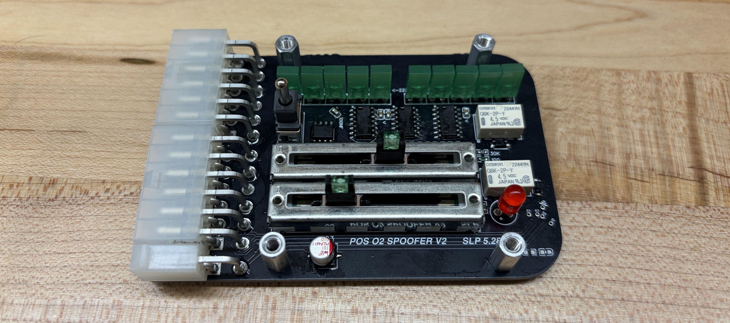
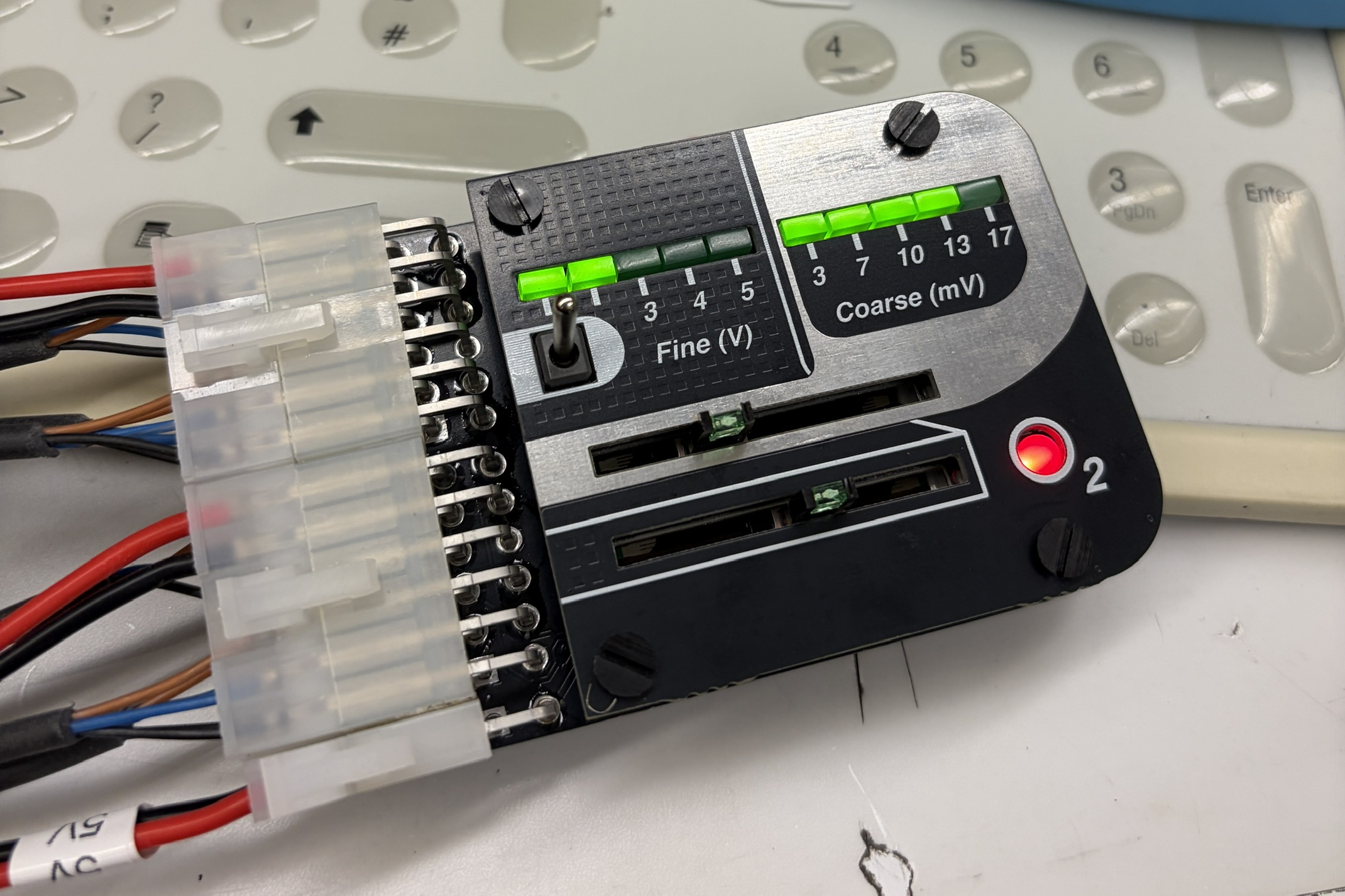
building an o2 sensor bypass device for an EOS M280
· electronics, research
.jpg)
in order to fire the laser in my lab's EOS M280 LPBF metal 3D printer, the oxygen content must drop below 0.2%. unfortunately, it's an old machine and struggles to pump the oxygen content down that far. it also takes a while to even get close to it. my thought was to build a device that can sit between the sensors and the control computer that gives the user an option to either let the signals pass through directly or supply some sort of fake signal that represents a lower oxygen level. doing this fully analog was a goal of mine, for reliability and simplicity purposes.
the EOS M280 uses 3 Maxell coarse o2 sensors that each produce their own small voltage with an internal galvanic cell. sitting in regular air, these sensors produce roughly 16 mV. When the machine's oxygen levels are pumped down properly, they produce only around 1-2 mV. once the oxygen levels reach a threshold that I believe to be at 1% oxygen, the system switches to a more complicated current-based fine oxygen sensor. luckily, the company that makes the fine sensor also provides a control board for it, that turns the current reading into a stable 0-5V depending on oxygen percentage.
at this point it's pretty simple. I had to create a controllable 0-5V signal and a 0-~15mV signal. I'd like to be able to see what voltage im outputting, and I'd like to be able to toggle the system between active and the regular pass-through.
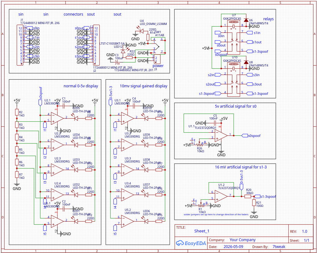
to control voltage, I opted to use 2 slide potentiometers for coarse and fine voltage, respectively, to supply a 0-5V signal for each channel. these outputs go into an op-amp follower circuit to prevent loading, and that output is indicated by a series of leds. i decided to go with a voltage 5-level indicator using a comparator voltage ladder, where 5V is stepped down to 4, 3, 2, and 1V thresholds. the comparators see if the output voltage is above that threshold, and if so the output is grounded, allowing for the completion of the respective led circuit. both signals are 0-5V, so to step one down to 0-15 mV I just used a simple voltage divider circuit with a 30k $\omega$ and 100 $\omega$ resistor which should result in 0-16.7 mV.
my first revision of this system was not great, as I improperly wired the potentiometers on the pcbs pretty badly.
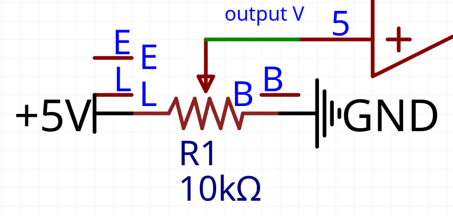
instead of hooking up the output to the wiper, I instead hooked up the output to where ground was supposed to be. I hooked up 5V to the wiper, and ground to where 5V was supposed to be. I also did not realize that the potentiometers that I ordered had led lights on them. since I believed the other pins to be duplicate pins as they appear in the footprint, I just hooked the duplicates together. the result of this was that when I plugged it in, both of the leds blew up and both potentiometers started burning up and attempting to catch on fire. I didn't want to wait for a new pcb to test the circuit, so I ripped the potentiometers out of the board and rigged up my one fresh one to the pads on the bottom of the board to keep going.
with this working, I hooked up the coarse sensor computer inputs to the board outputs and the 0-5V sensor input directly to the op-amp follower output.
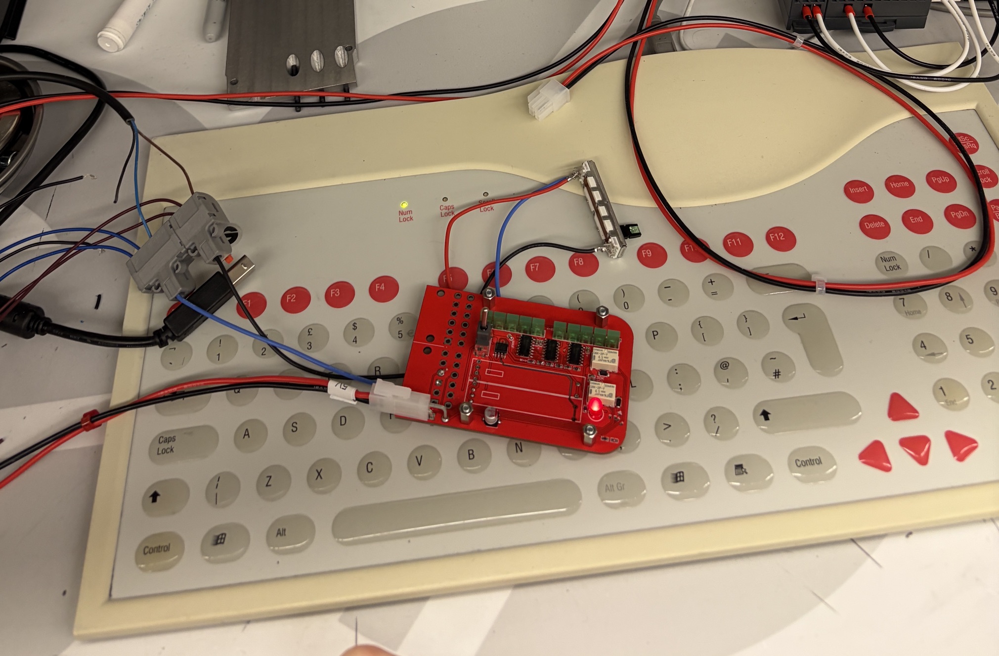
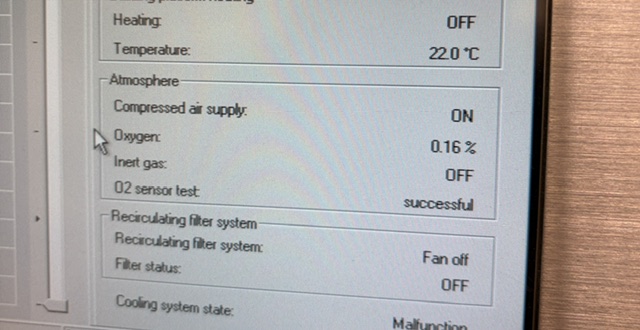
after turning the machine on and setting the o2 level really low, it worked! we should be able to fire the laser whenever we want now.
i fixed the wiring for the potentiometer in my next pcb revision. everything worked, except for the fact that I accidentally had the potentiometers backwards. thats okay though. it works!
.png)
to add the faceplate, i designed everything to be on the same board and just be broken off. the nubs can be filed off.