precision laser powder bed fusion testbed
· research, manufacturing, electronics
this project began with the need for a testbed to measure powder physics. typically powder analysis is done on powders themselves, agnostic of the machine in which they are used in lpbf systems however, it matters how the powder interacts with the specific recoater blade and the system as a whole. thi s testbed is to be made to represent an actual working environment in the most controlled way possible. we might add a laser to it at some point, but the purpose here is to understand the underlying process error sources with respect to powder topography and geometry.
i was given the design for the base slab, and the planned zaber stages for the necessary build and supply stages. the travel ranges were 20mm and 40mm respectively. to control the recoater movement, i opted to go with a teknic clearpath sdsk motor due to the integrated encoder and closed-loop system. to link all this together i opted to go with an esp32-s3 due to the wireless options and large ecosystem of support. the requirements i made up were that i wanted this system to work completely standalone like a machine tool, be fully controlled with g code, and allow file transfer over either wireless or and sd card. i also wanted some jog buttons, and naturally as a split ergonomic keyboard nerd i opted to go with hot swappable choc v1 mechanical switches.
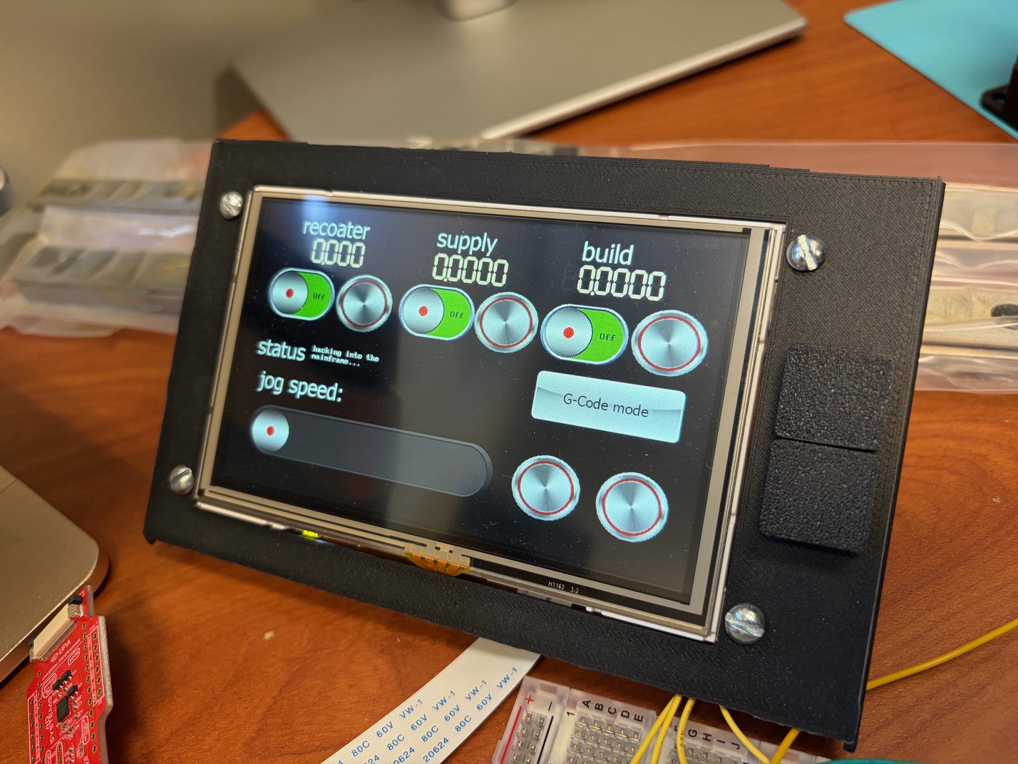
the system constraints with the given motion systems were that the teknic motor communicates via rs232, and the zaber stages use uart but at 5V. the esp32 just has 3.3v gpio pins, so some logic level shifting was necessary. i decided to go with some bss138 mosfets for level shifting to 5V and a max3232 ic for rs232 shifting. i bought some breakout boards for each off digikey and put it all together on a breadboard, with some wires soldered to the keyswitches. the sd card just uses spi so that was easy to add. for the interface, i went with a 4d systems display that holds the ui locally and allows values to be input and displayed over uart. basically you give the object a name in the ui designer and change its state via uart, or change its value in the display and it will update the object to the mcu.
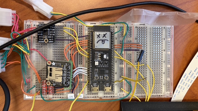
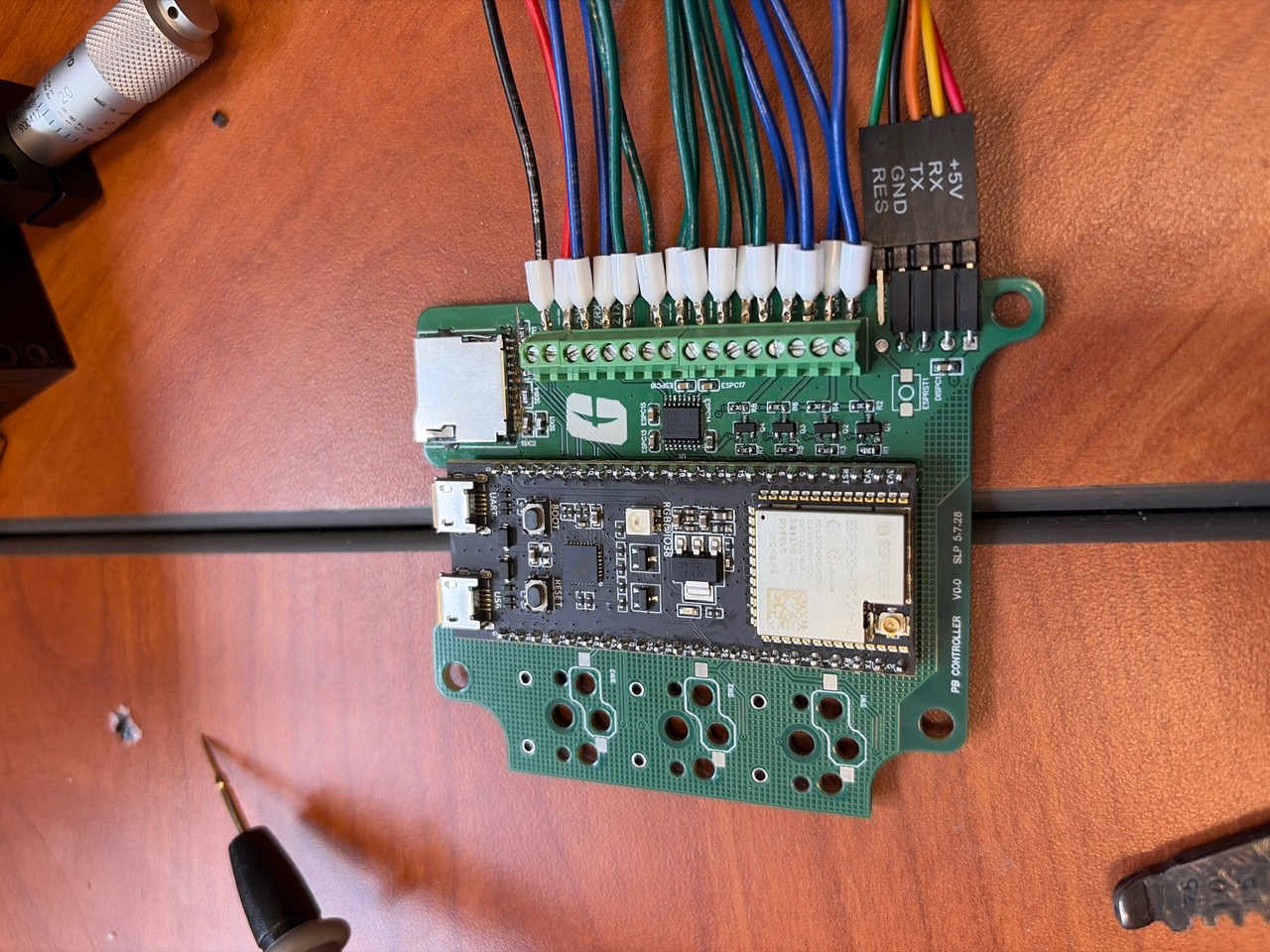
it came out looking really nice. unfortunately that does not correspond to actually working. as soon as i hooked it up everything seemed to work, but when i plugged in the sd card everything shut off. I somehow mixed up the vcc and ground pins on the sd card, so the whole board was shorting whenever i plugged the card in. for the time being it worked with no card plugged in though.
i fixed the wiring for the pcb and ordered another. i soldered everything in place, and unfortunately the sd card still did not work. after some debugging i found that the miso pin was hooked up wrong. by jumping the correct pin to the one i thought was the correct pin, i was able to make it work. i used a really janky jumper wire to do so:
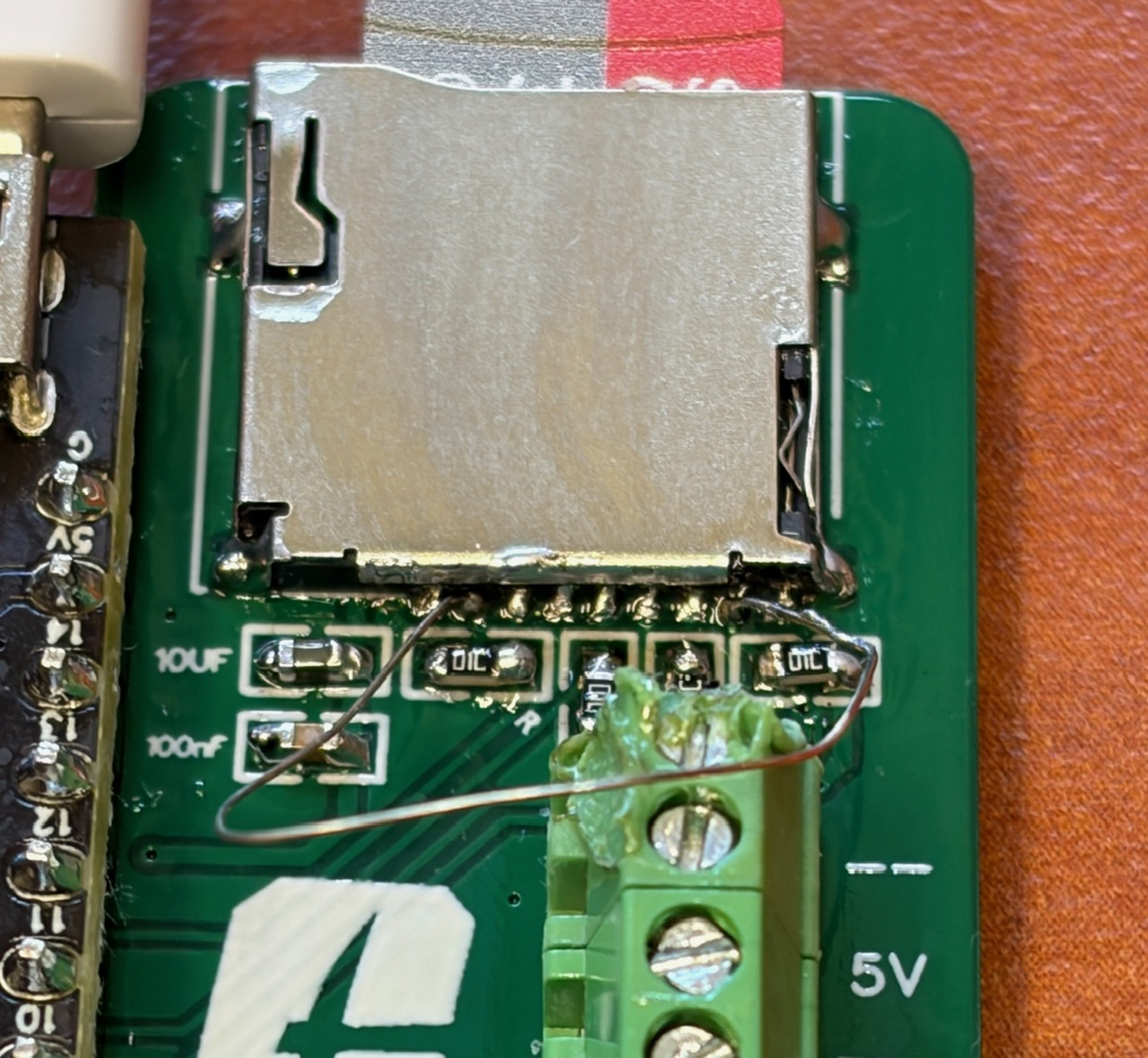
this worked but was definitely not the solution that i wanted to stick with. instead of resoldering and redesigning everythig, i made a quick 10 minute 'oopsie' pcb that fits where the sd card slot would normally be, and have the jumper wire built in. using castellated holes i could mount the pcb like its an sd card slot, then solder the sd card slot on top of that.
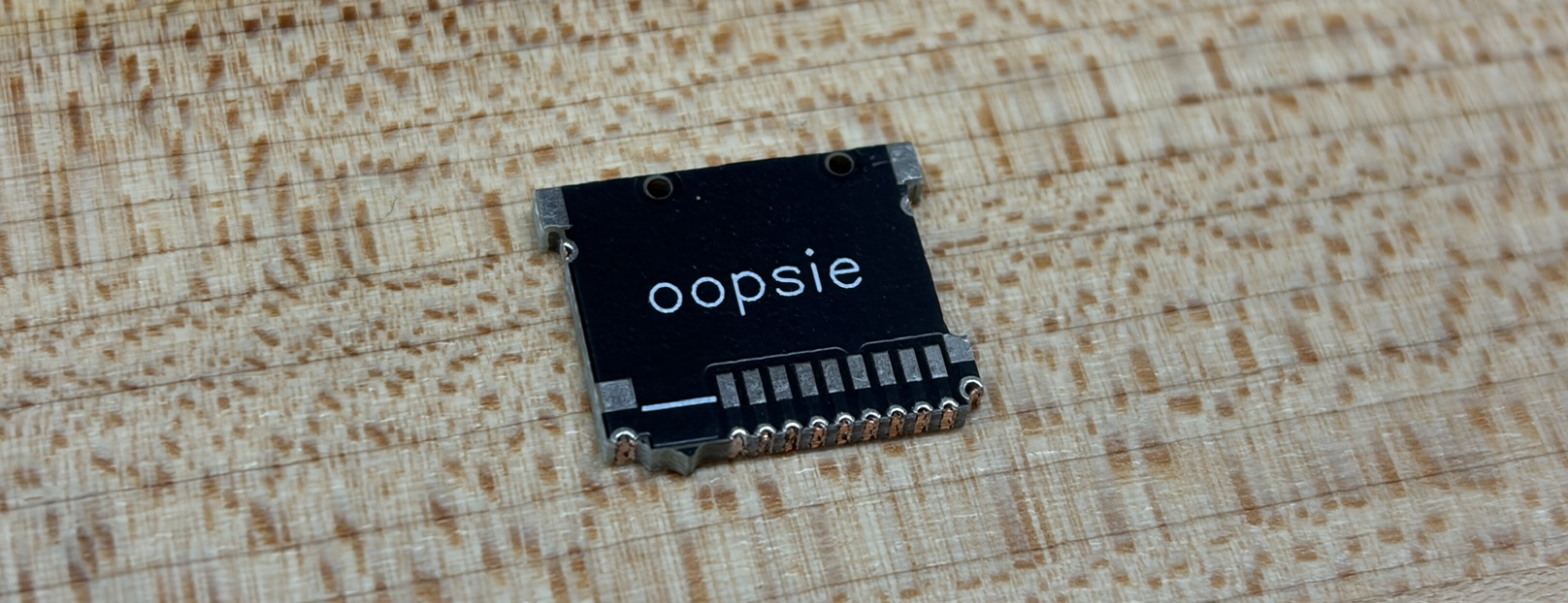
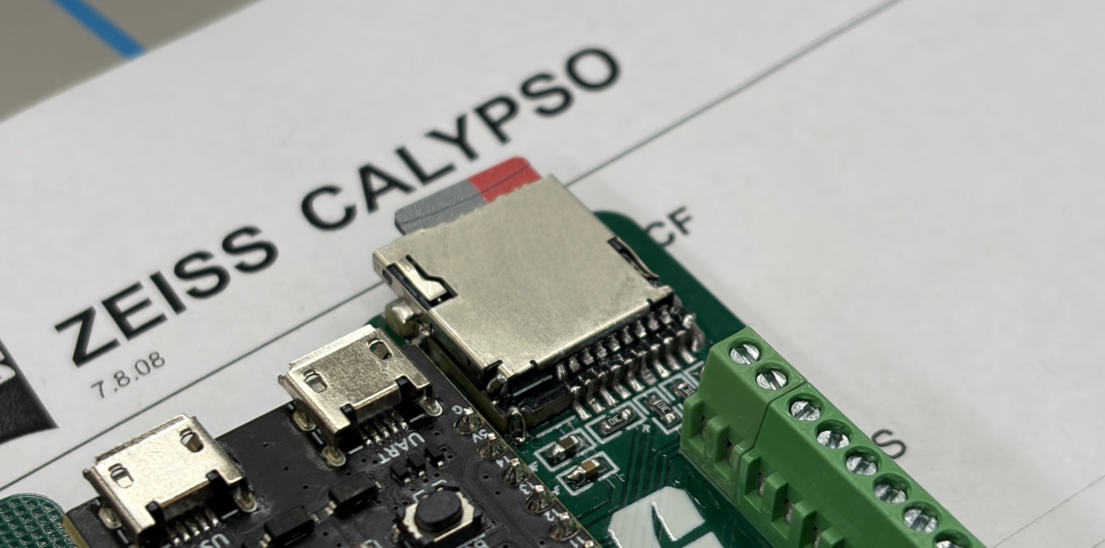
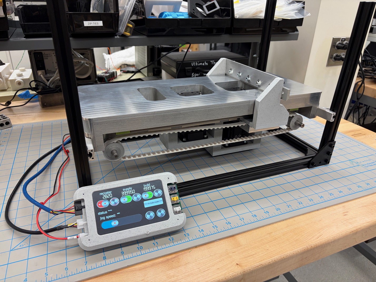
this solution was much more elegant. and it worked! with that part figured out, i made a screen and controller mount/cover, and installed all of the components
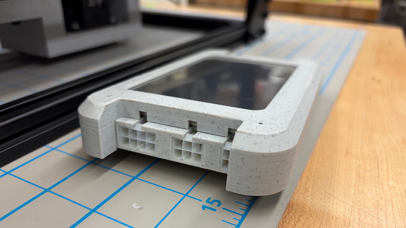
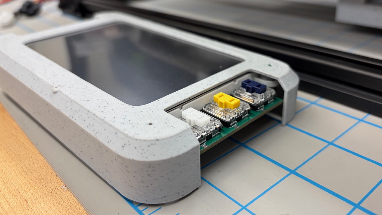
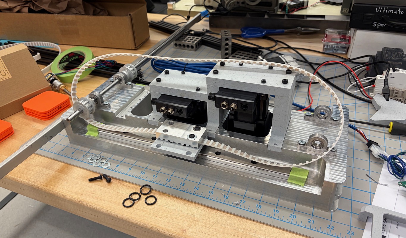
with the electronics figured out, i pivoted towards the mechanical assembly of everything. i 3d printed all of the stage mounts i made, but they were designed so that I can manually machine them later easily. this goes for the recoater blade mount as well. the recoater is constrained to 2 misumi guide rails, and the top deck of the machine was milled to a 6-8 $\mu$m flatness so that we know for sure that the distance from recoater blade to nominal powder surface stays the same.